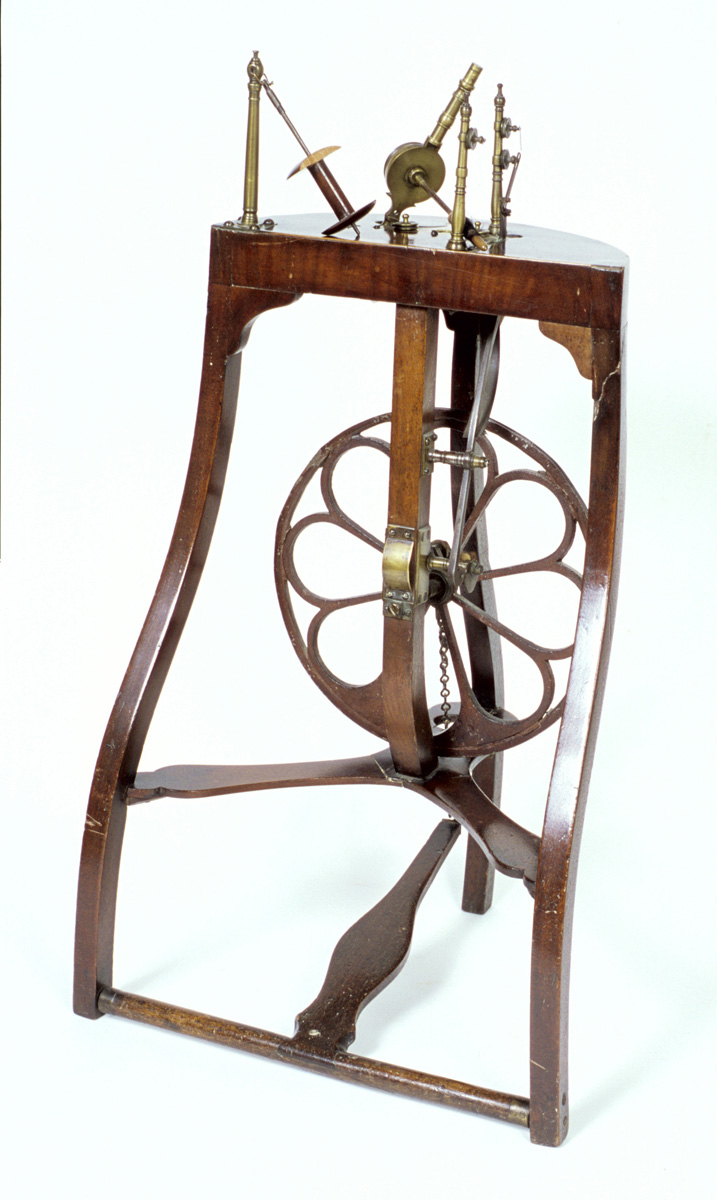
Putnam, Porter wheel head B

Close-up of label on wheel head. Photo courtesy of Craig Evans.

Label on wheel head. Words are hard to decipher though the words wheel heads and the names Putnam, Porter, & Leonard can be seen.

Hartford Courant 1813 B Putnam Porter Leonard

Newspaper announcement from Hartford Currant from September 1813.

Old fashioned newspaper print. It reads in part:
Merchants, Farmers and Mechnicks
TAKE NOTICE
All persons are strictly cautioned not to make, use, or vend to be used Miner’s Patent Accelerating Wheel-Head or any part of this improvements of same unless by permission of Putnam, Porter & Leonard….
Hartford Current, September 14, 1813.

CA – Figure 12 B

Accelerating wheel head without a spindle

Accelerating wheel head without a spindle has two uprights or maidens, with the accelerating wheel or pulley between them, and a thin rod between the maidens above the pulley.

CA – Figure 8 B

Accelerating wheel head with extension to the maidens

Accelerating wheel head with a spindle attached to base. Turned maidens have the accelerating wheel or pulley between them but the maidens have extensions that form a hoop over the accelerating wheel.

CA – Fig. 1 B

Diagram of standard accelerating head

Standard Miner’s head with parts labeled so that one can see how the parts were measured. Diameter of large pulley, diameter of small pulley, length of spindle, length and diameter of mother-of-all, height of maidens.

Figure 2a B

Study wheels showing the single leg, table end, spindle post and on some the maidens to hold the spindle.

Row of six images of great wheels from the end of the table showing the turnings on the single leg, the spindle post and wheel heads on one, two, four and five. The turnings on the components of the three on the left are fairly simple, the three on the right are more ornate. 

EVA Figure 11 B (1) spindle posts

Study wheels showing table and spindle posts.

Two rows of images showing the end of a table with the spindle post. The top three have a tension screw that goes through the post to a receiver. The first one is missing the tension screw. The lower row have very ornately turned spindle posts but no tensioning device.

EVA Figure 3 B back legs

Study wheels showing two legs and the end of the table.

Two rows of images showing the end of a table with two legs. Top row the turnings on the legs are fairly simple, on the bottom the legs have more turnings and the legs are thinner on the ends.

EVA 2 B wheels overall

Six great wheels in study

Six great wheels in two rows, Wheels on top row have slanted table, a drive wheel with fourteen spokes except the third, on the second and third there is a brace between the drive wheel post and the table, the single leg is at the left end of the table, then the spindle post and wheel head, with a tension screw through the spindle post.

The lower row all the wheels have a slanted table with ornately turned legs, a drive wheel with fourteen spokes, a brace between the drive wheel post and the table, the ornately turned spindle post is at the far end of the table, and the top of the single leg comes through the table to the right of it.

ThomsJamieson_SpinningWheel_1 B wiithdistaff_Photo1v1

Double-flyer wheel, restored

Low spinning wheel with treadle. Rectangular table with three simply turned legs with treadle between front legs: two slanted uprights hold drive wheel with sixteen spokes at right end. Footman visible behind drive wheel. Tension screw set into left end of table. Mother-of-all holds two short posts, two parallel turned rods are attached to the posts, the two bobbin/flyer units fit between the rods. Two separate drive cords connect each bobbin/flyer unit to the drive wheel. All three parts of the distaff are present, set into the upper left corner of the table.

THmasJamieson 3 B_DoubleFlyerDetail_3v1

Detail of two bobbin/flyer units

Two U-shaped bobbin/flyer units attached next to each other on spinning-wheel table. Orifice ends fit into bearings on turned rod in front, back end of shafts fits into another turned rod that is parallel to the first. Drive cords can be seen. Right hand bobbin-flyer unit set back slightly, so drive cords don’t tangle.

metal 2 B both 45 degrees

Two Swedish upright metal wheels

Metal wheel on left has trapezoidal bottom frame on small feet. Back upright is elliptical with reinforcing piece at top. Front part of frame is sloping A-shape with the treadle between the bottom parts. At top of frames is mother-of-all that holds wooden bobbin/flyer unit. Drive wheel resembles bicycle wheel. Drive-wheel axle with footman fits between back upright and crosspiece of front frame.

Metal wheel on right has triangular bottom frame on small feet and treadle. Back upright is straight with reinforcing piece at top. Front frame is in two parts, lower art is trapezoidal, upper part is triangular. At top of frames is mother-of-all that holds metal flyer with wooden bobbin. Drive wheel has six spokes. Drive-wheel axle with footman fits between back upright and crosspiece of front frame. Distaff attached to side of mother-of-all.

Platt 10 B bobbin winder IMG_1207

Bobbin winder marked J. PLATT

Bobbin winder has a rectangular table with three turned legs. On right hand side a single, tall, turned post holds a drive wheel with ten spokes and a flat rim. On the left side a rectangular wooden box, taller on the short sides, is attached to the table.

Platt 1 B – single flyer IMG_1251

Brenda’s family’s J. PLATT spinning wheel

Low spinning wheel with treadle. Rectangular table with three turned legs: at right end two slanted uprights hold drive wheel with twelve spokes. At left end a tension screw fits into table. Mother-of-all holds two turned maidens with bobbin/flyer unit. Two parts of a distaff are present. On front side of table mark J. PLATT.

Platt 6 B great wheel IMG_1218

Great wheel marked J. PLATT

Large spindle wheel has rectangular table with three turned legs. On right hand side a single, tall, turned post holds a drive wheel with twelve spokes and a flat rim. On left end two small turned posts has a barrel tensioner between them that holds a bat’s-head spindle head.

Platt 4 B winder front 2

Reel marked J. PLATT

Reel or skein winder has slanted table with three turned legs, two on the right and one on the left. The table leans toward the right. At the top of the board attached to the back of the table is the box that contains the gears. On the front of the box is a hub holding five turned arms with small knobs at the ends.

Platt 8 B double flyer

Platt 8 B double flyer

Double-flyer wheel has rectangular lower table with four turned legs. Treadle set between two front legs. Four tall posts hold upper split table. Two shorter posts hold the axle of the drive wheel that has twelve spokes, On upper table two maidens hold front of the bobbin/flyer units. Back of flyer shafts fit into board on rear section of upper table. Two parts of distaff are present, set into rear section of upper table.

SA 13 B front overall

Wheel with the tension system on the tabletop

Violin shaped table has three turned legs, regular treadle and footman. Slanted wheel posts hold drive wheel with eight spokes. At other end two short bulbous posts support a turned crosspiece that holds the tension screw and has a hole for a distaff. Two parallel rods come out of this crosspiece and fit through the mother-of-all to the wheel-support posts. The threaded screw goes into the mother-of-all and can change the position of the mother-of-all to adjust the drive-band tension. The area of the rods between the crosspiece and the mother-of-all is smooth, but on the side by the drive wheel they have turnings that limit how far the mother-of-all can be moved.

SA 5 B tension screw

Detail of tension screw

Tension screw goes through the supported crosspiece and into the mother-of-all but the maidens and bobbin/flyer unit are not present. Two smooth dowels on the sides of the tension screw fit through the mother-of-all.

Double rim wheel 15 B overall side

Wheel with three-armed flyer and drive wheel with two rims

Plain rectangular table held by three ornately turned legs; a wooden cut-out is between the legs under the drive wheel; footman on right side of drive wheel. Drive wheel has two rims with short spokes between them. ornately turned maidens have a wooden bridge above them and all three parts of the turned distaff are present.

Double rim wheel 12 B drive wheel

Detail of drive wheel with double rim

Drive wheel with outer rim then short spokes and an inner rim. Spokes and half spokes fit between the inner rim and the hum. Top of the inverted U-shaped support post has a short turned piece with a slot for the drive-wheel axle with a wooden peg to hold it in place.

Double rim wheel 4 B flyer

Detail of bobbin/flyer unit

A hand holds the bobbin/flyer unit with whorl on left and orifice on right. Thumb is on one of the flyer arms, other two are below to the right and above to the right. Thread comes from bobbin along side the thumb and through the orifice.

sc swift 3 B holes top IMG_7746

Detail of cage on squirrel-cage swift

Horizontal rod fits over square post. Two short posts hold a cage comprised of two disks of wood with dowels in between. Three holes are seen on the side of the rod.

sc swift 1 B IMG_9637

Squirrel-cage swift

A low base holds a squared post to one side; At the bottom is a movable horizontal rod that fits over the post and holds a cage, which is comprised of two disks of wood with dowels in between. It is facing down. At the top is another movable horizontal rod with a similar cage, facing upwards.

KMW 1 B My 2nd Dominy wheel

Dominy great wheel

Simple rectangular table on three turned legs; drive-wheel post on right end; drive wheel has ten spokes around hub but one is missing, flat rim. Spindle post at left end is gently curved has a barrel tensioner on one side, with the screw to fasten it on the other.

Dominy spindle post B

Spindle post on Dominy wheel

Post curved on the bottom but round on the top, has a barrel shaped piece set through the side of the top section; threaded at the other end with nut.

Stiles patent to leaper B

Advertisement for Stiles Patent pendulum wheel

Old newspaper from Truro, Nova Scotia, dated May 23, 1808. Headline reads “New Advertisements. Stiles’ Patent Spinning Wheel Archibald, Leaper, & Co.”

Stiles and Trite wheel B MS09

"Stiles and Trite" wheel

Table with four legs holds two uprights; the one on right is low, the one on left is two thirds taller. A board goes across the uprights. A drive wheel is attached to the right-hand end of that board. At the top of the taller upright is a pendulum arm with a spindle on the end and a counterweight at the top.

corn husks 23 B

Corn husk bearings on accelerating spindle head

Fresh braided corn husk bearings hold a metal spindle next to the base of an accelerating head that has one post to hold the accelerating wheel at the top.

corn husks 15 B

Banding the corn husk braid

Right hand at top holds metal spindle in front of base of Miner’s head, corn husk braid is bent around metal. An awl is in the left hand at the bottom.