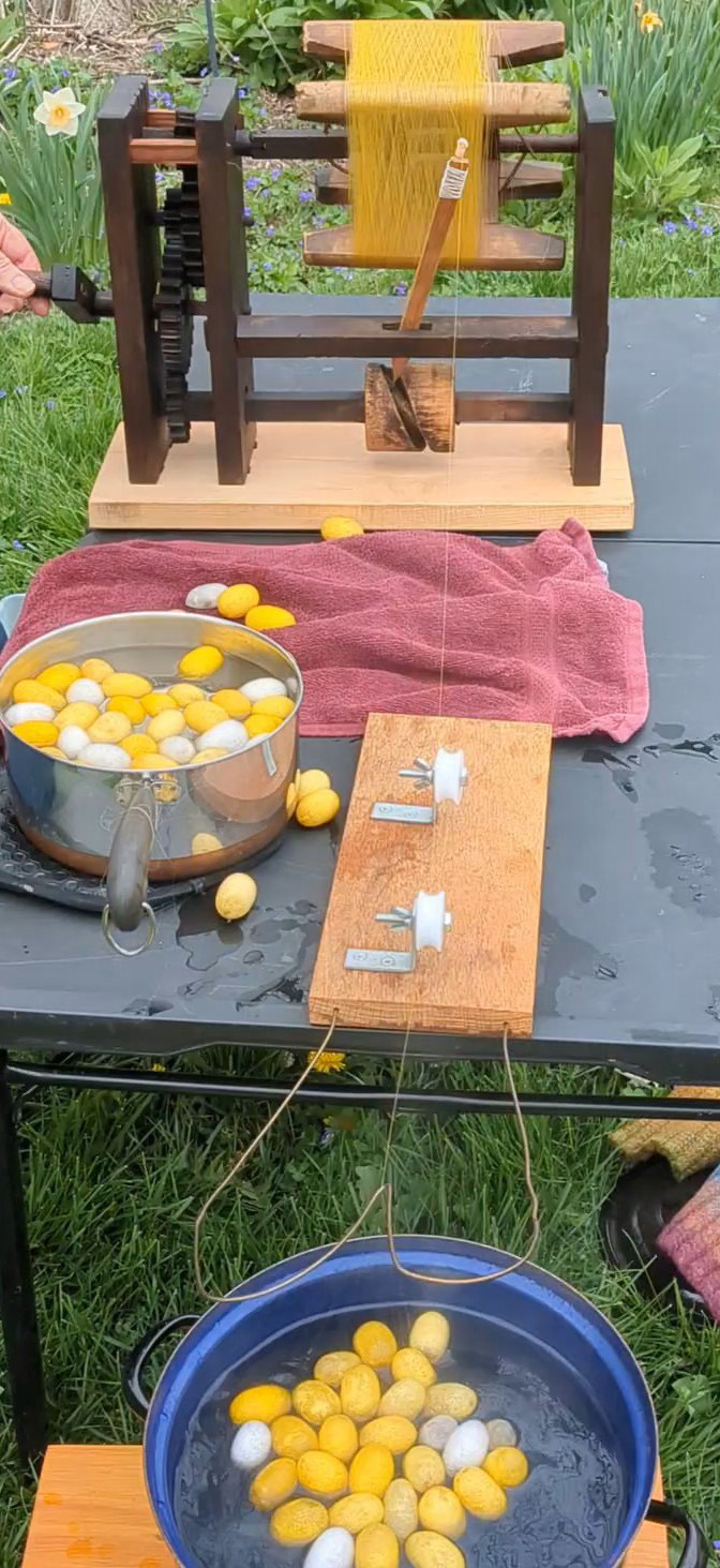
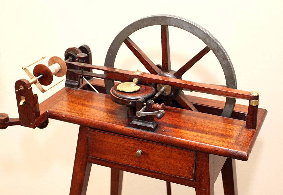
Restored Zaguri 5. From bottom basin of water holding degummed cocoons, silk fibers drawn up over two plastic pulleys to rocker arm that is putting the threads on the itomaki (bobbin) of the zaguri (reel).
images for issues
Restored Zaguri 5. From bottom basin of water holding degummed cocoons, silk fibers drawn up over two plastic pulleys to rocker arm that is putting the threads on the itomaki (bobbin) of the zaguri (reel).
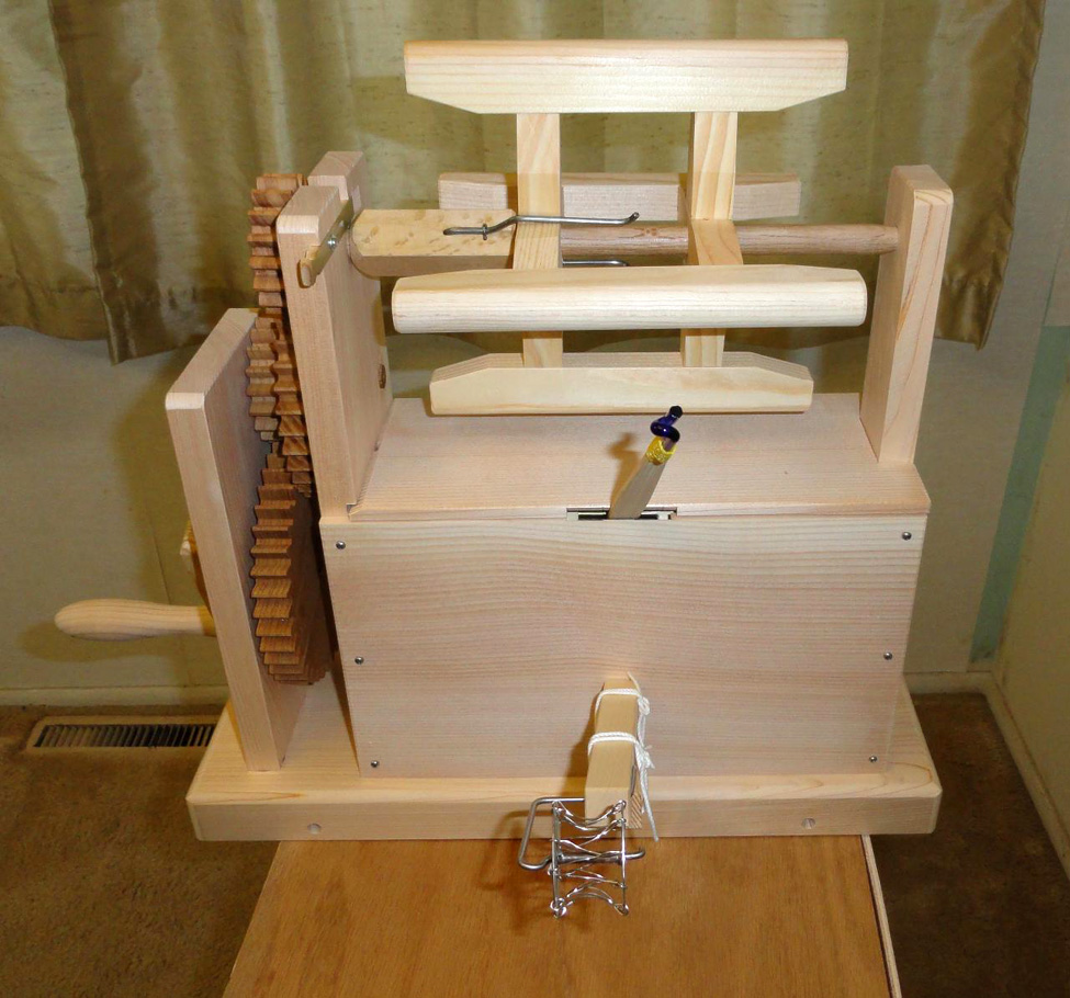
Zaguri 4: modern zaguri. Light-colored wooden box with gears and handle on the left. At top two posts hold axle rod and itomaki. A rocker arm sticks out of the box, and a small metal pulley is attached to a wooden piece on the lower outside of the box.
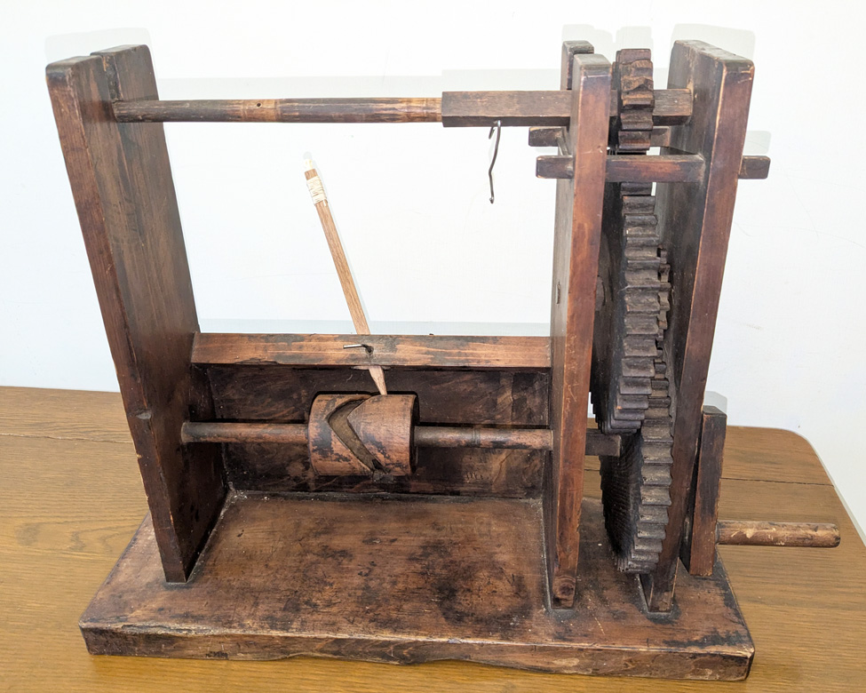
Zaguri 2 from Kumamoto has a wooden base with three vertical sides. A set of gears with a handle fits between the two on the right side. The axle rod for the itomaki is on the top. Near the bottom is a rod holding a cam with a rocker arm.
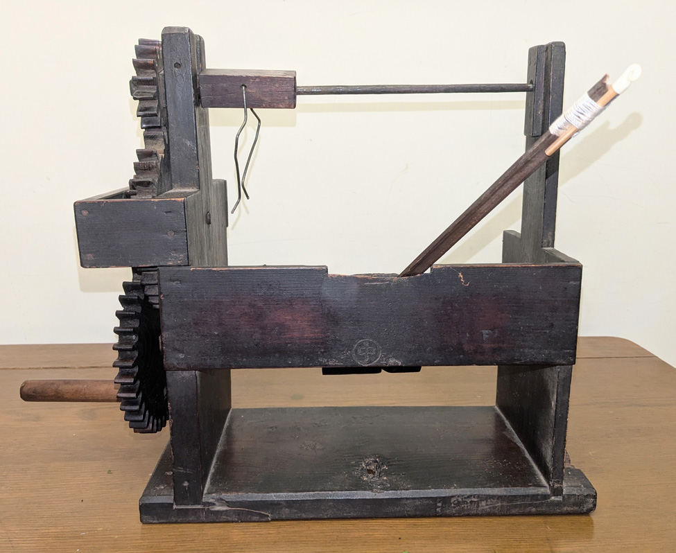
Zaguri 1 stamped “Atari” has a wooden base with two vertical sides. A set of gears with a handle are on the left side, a rod with a piece of wood and short pieces of metal on the left goes across the top. A rocker arm sticks out from the back. The wood is dark and looks old and well-used.
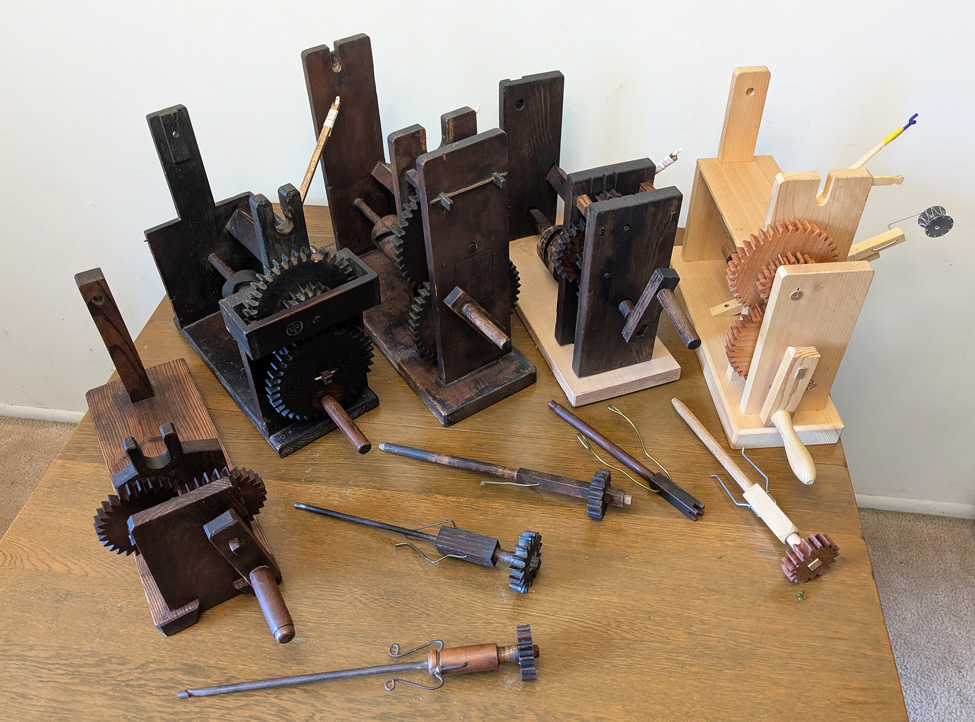
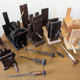
All are wooden structures with gears on the side, shown without itomaki, with the top gear and axle rods removed. The four on the left are antiques, made of very dark wood that appears to be stained or treated, though the farthest right of these appears to have a replacement part made from much lighter wood. The last on the right is modern and is made of very light wood.
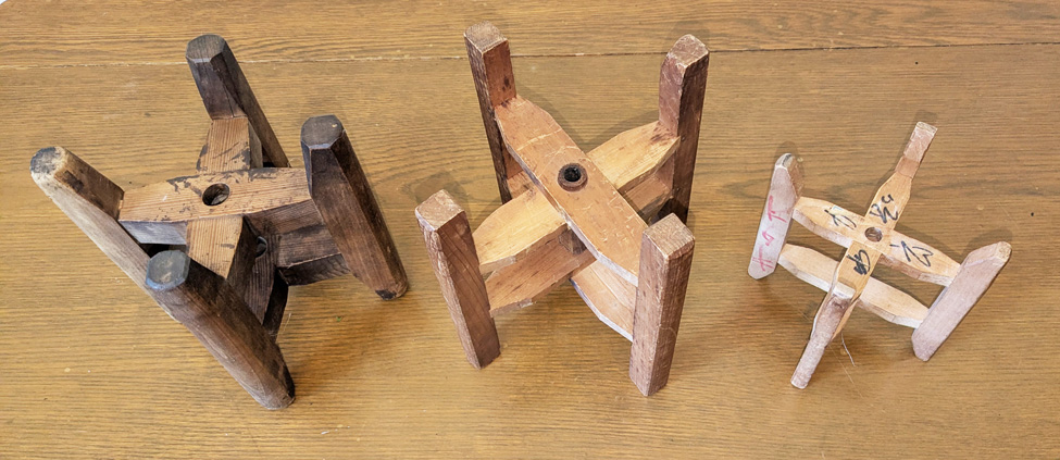
Hollow wooden rods have two pair of cross pieces that are held in place by four wooden arms on the ends. Two on the left are larger than the one on the right.
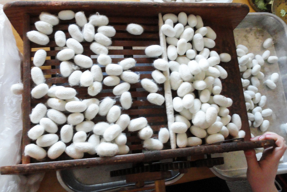
Top tray of kebatoriki showing how the cocoons move and the fibers that are caught on the rod. On the left a metal pan holds more cocoons.
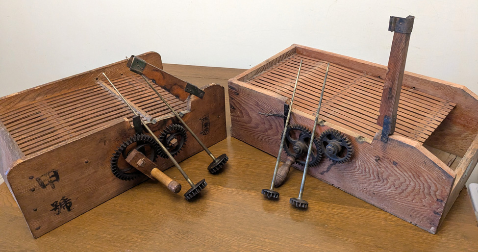
Two kebatoriki showing the left side of each one with the gears and handles. The hinges are up and and the brass rollers, with gears on the ends, have been removed.
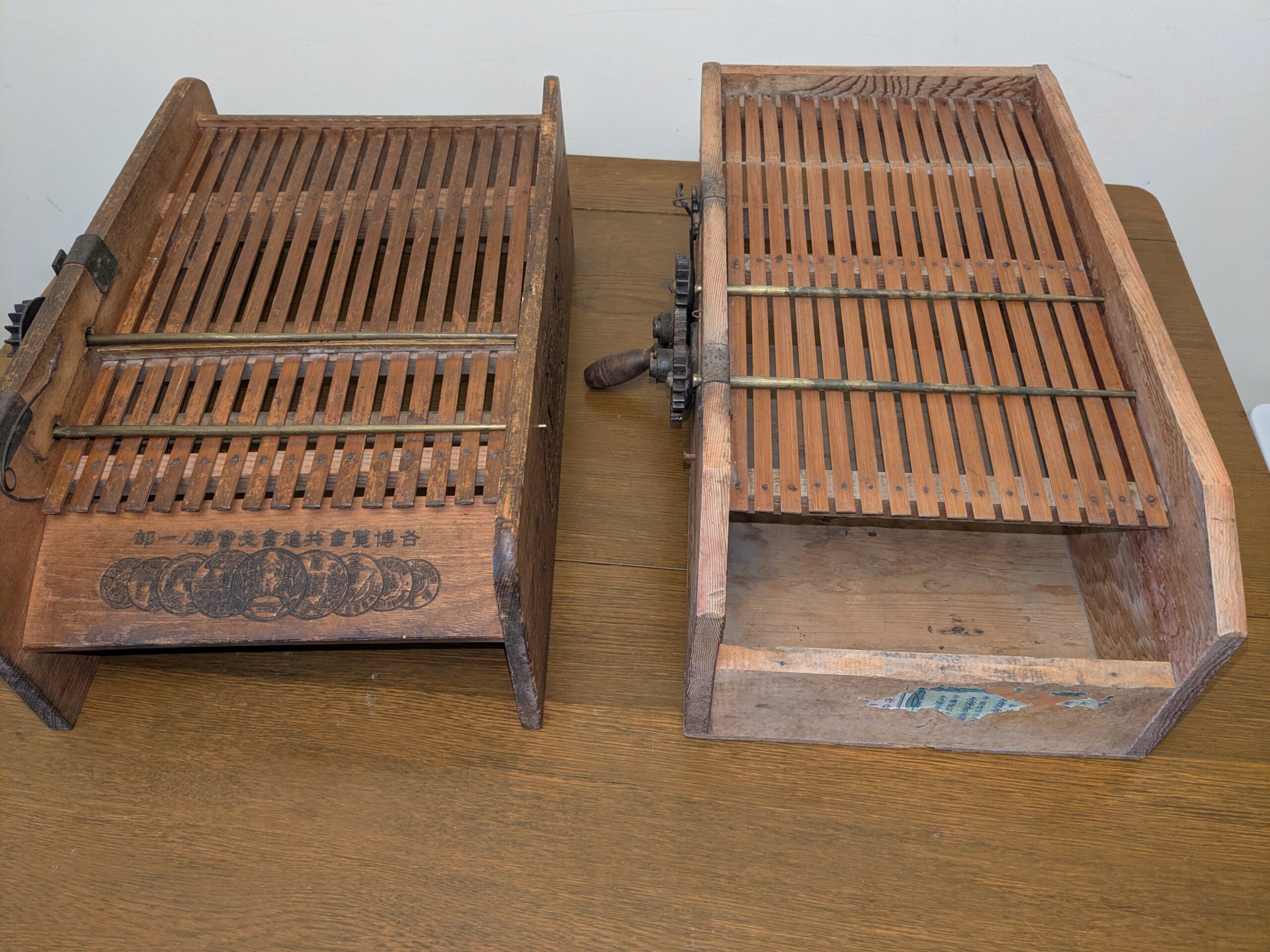
Two kebatoriki: Two rectangular wooden boxes with a layer of thin, evenly-spaced slats parallel to the sides. Each has two metal rods that go across the slats to the sides of the box. There are Japanese characters and circular stamps on the front edge of the one on the left. The one on the right has what appears to be the remains of stuck-on paper, possibly a label, on the front.
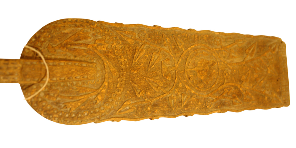
Detail of paddle-shaped top of a wooden quenouille showing the carving.
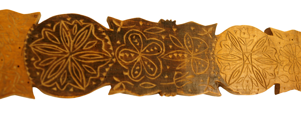
Detail of section of a quenouille showing the carving: a round section; a rectangular section with pointy edges; then another round section. All sections have flower designs.
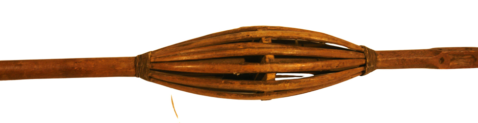
Close up example of a quenouille showing splints bent over a notched disc attached to the wooden shaft where the flax fibers would be attached.
![Lithograph of c. 1880 watercolor by Walter Satterlee [1844–1908] of a young Breton woman spinning.](https://spwhsl.com/wp-content/uploads/2026/08/French-3-B-2-walker.jpg)
Lithograph of c. 1880 watercolor by Walter Satterlee [1844–1908] shows a woman walking along the shore, with a boat in the background. She has a spindle in her right hand while her left hand pulls the flax fiber down from the distaff tucked into the belt of her apron.
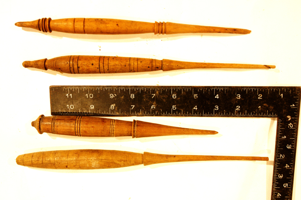
Four examples of fuseaux, turned or, more usually, carved sticks of wood, typically 8″ to 10″ (~20 to ~25.5 cm) long, that tapers to a point at one end and widens in thickness to nearly a bulbous shape. Includes a ruler for scale.
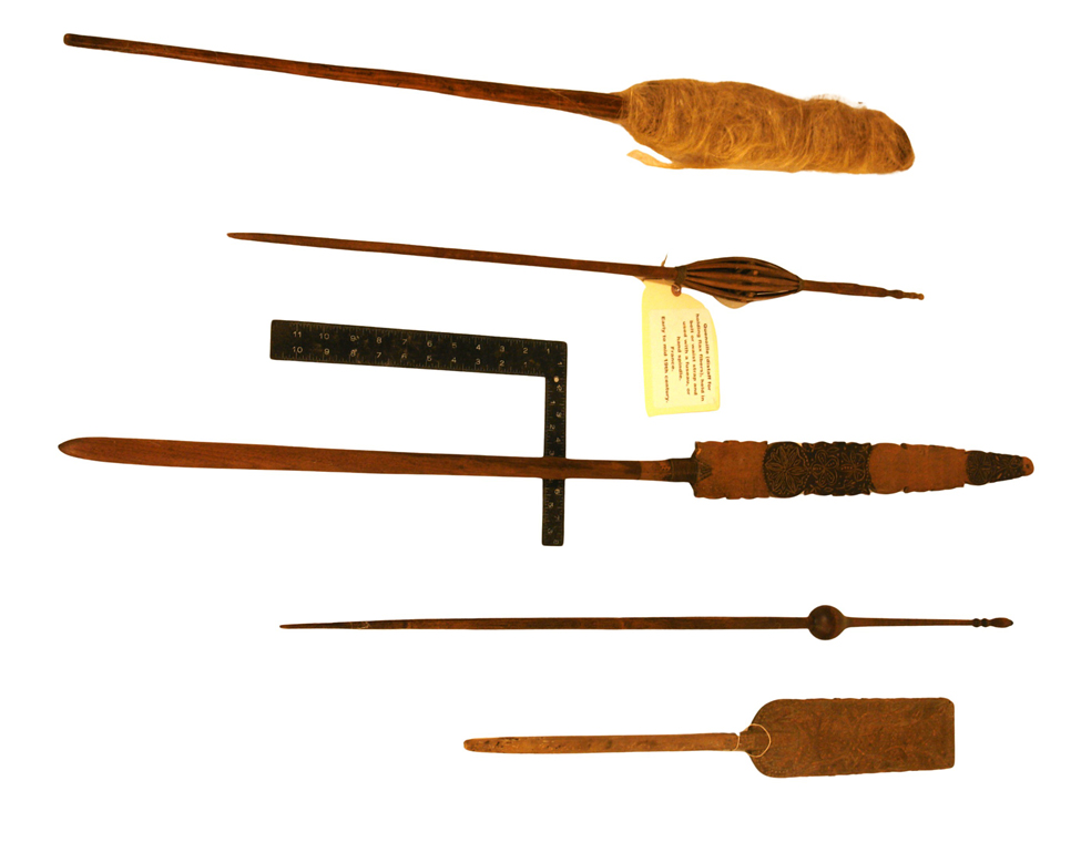
Five examples of quenouilles ranging in length from 24″ to 40″ (~61 to ~102 cm) typically with a tapered end that fits into a belt, skirt, or apron. The top one has flax on it. The others show the different forms that the top can take in two cases carving. Includes a ruler.
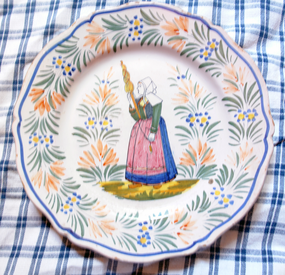
A plate rests on a checked fabric. A design of blue flowers and stems circles the rim of the plate. At the center is a woman holding a spindle in her left hand. With her right hand she is pulling on flax fibers wound on a distaff that is tucked into her belt.
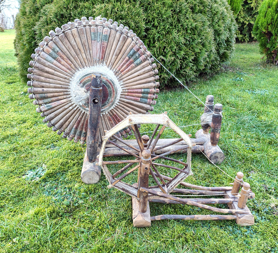
Two spindle wheels both somewhat crudely made, the one in front much smaller than the one in back, it also has fewer spokes. The one in back has a large number of spokes, some still show signs of being painted.
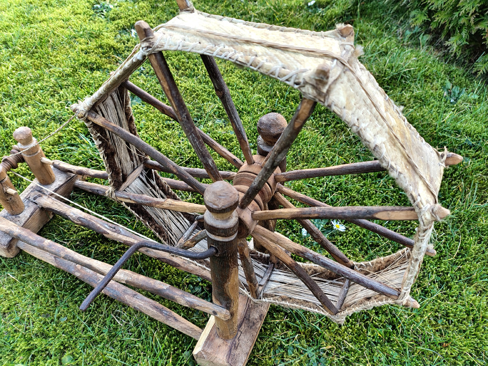
Spinner-side view of the drive wheel on the Berber wheel shows a sheepskin rim attached between the two pairs of crude spokes, with a cotton drive band around it, and an iron handle that goes through the front support post through the hubs into the back support post.
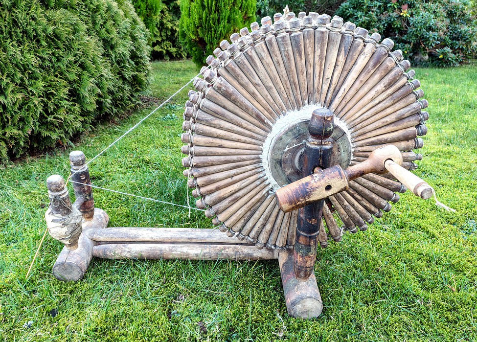
Spinnner-side view of wheel found in southern Turkey shows a pair of short posts on the left for the spindle and tall posts on the left to hold the drive wheel. The post are set into logs as bases. The drive wheel consists of two sets of spokes laced together, a covered hub, and wooden handle in three parts.
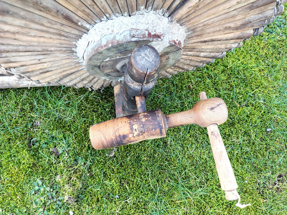
Detail of drive wheel hub covered with what appears to be paper pulp and the wooden handle that has three turned parts.
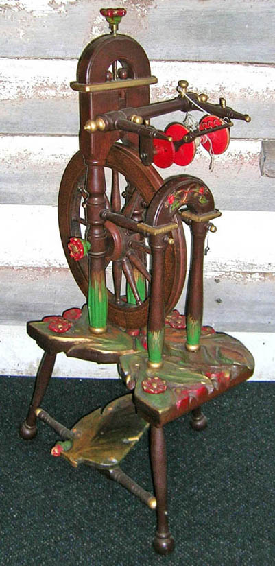
Upright wheel with three legs and treadle under a painted table. On the left of the table the drive wheel is held by a pair of turned and painted posts that have a curved wooden piece on top. The mother of all with horizontal maidens and a bobbin/flyer unit is attached to that piece of wood. Another pair of turned posts with a curved piece on top is on the right-hand side. There are red flowers and gold paint on some parts.
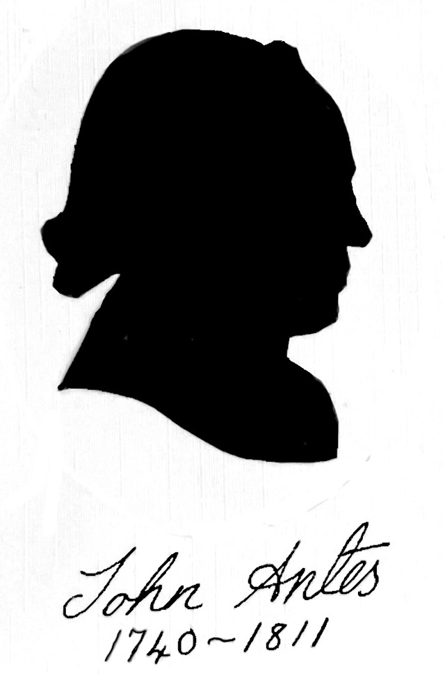
Silhouette (side view), of a man’s head; appearance indicates that it is from the 1700s or early 1800s.
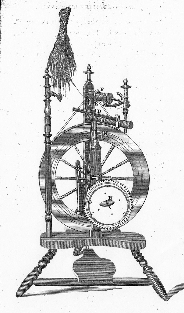
Engraving of an upright wheel with a spoked drive wheel. The bobbin/flyer unit is above the wheel, a dressed distaff is set into the left side of the table and a clock face mechanism is on the right side.
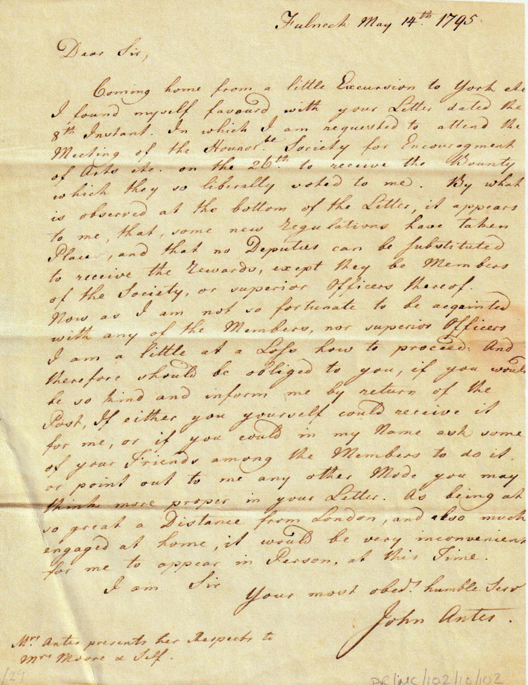
Handwritten letter by John Antis letter dated 14 May 1795. Begins “Dear Sir.” He thanks them for the “bounty,” a cash prize, but asks if someone else could pick it up for him “As being at so great a distance from London …. it would be very inconvenient for me to appear in person at this time.” Concludes “Your most obedient humble servant
John Antis”
Tabletop of John Planta wheel showing the spoked drivewheel with a metal rim set into the table. A bobbin/flyer unit is on the left and an Antis mechanism is in front of the drive wheel.

Index of The Spinning Wheel Sleuth issues 1-129

A triangular table has a flat board nailed to the left side. A spoked wheel is held by turned rods that are set into the board. At the top of the board is a spindle held by a short turned post.

Close-up of the spoked accelerating wheel. The hub or whorl on the right side of the photo has a thick groove for a clothesline rope which goes to the pulley attached to a post. The groove on the accelerating wheel itself, on the left side of the photo, carries the lighter-weight drive band that goes to the spindle.

Close-up of movable board that holds short spindle post with spindle attached below it. Drive band from accelerating wheel goes around the whorl on the spindle. A large nut holds the movable board in place.

Side view of box type tape loom carved and painted light brown with green leaf designs, date of 1849 in yellow, nicknamed the “cradle loom” in the collection of Versterheim Norwegian-American Museum. Ratchet and pawl on upper right hand corner. Warp with small section of weaving visible at top.

Reproduction of “cradle loom” by Merlin Lee, painted light blue with flowers and leaf designs on each side of the ratchet and pawl in the middle. It has a warp with some weaving and a shuttle on top.

Overhead view of an unpainted reproduction of a “cradle loom” showing the warp going through a rigid heddle and shuttle in the warp.

Rectangular shallow wooden boxes joined by a metal hinge.Two circular discs of different sizes on the right-hand side, a spindle on the left-hand side. A band goes from the larger disc to the smaller one and another band goes from that disc to the spindle.

Line drawing with title “Accelerating wheel head” at top shows an accelerating wheel with grooves on right held by two small posts set into a round rod with threaded screws under them. A spindle is held by bearings. That rod held by a post set between two posts. Part of a band goes around the grooves of the accelerating wheel, and another goes around the outside of the wheel to a whorl on the spindle.
![Spinning wheel marked B. SANFORD, by Beardsley Sanford [1790–1868]](https://spwhsl.com/wp-content/uploads/2026/03/Sanford-df-1-B-overall-IMG_0773.jpg)
Overall view of spinning wheel marked B. SANFORD, by Beardsley Sanford [1790–1868] showing two treadles, two wheels, two bobbin/flyer units, and a pole distaff.