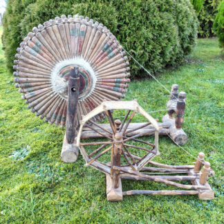
Wooden base holds a table with two legs on the left and one on the right. A slanted post on the right holds a drive wheel with four spokes. On the left is a round post holding two lace bobbins. A drive band connects the bobbins to the drive wheel.
Media Category: issue
images for issues
Figure 7 B (2)
Long, rectangular wooden box, not very deep, has on the right two rectangular posts that hold a solid wooden drive wheel with a wooden handle. At the middle are two turned posts with a bobbin in between them. A drive band connects them to the drive wheel. At the left end is a wooden extension with a short post with two slats that cross in the middle. Old bobbins fit into the four ends. It is used as a swift to unwind the thread.
Figure 12 B (2)
An elaborately turned post has a short turned extension that holds a matching post. A wooden pulley fits between the posts and a handle is attached to the wheel axle. Above the wheel is a small turned pieces and above that is a metal rod with a grooved piece of wood on it. The metal rod goes through the wooden upright on the right and a bobbin is attached to it. A drive cord goes from the pulley to the grooved piece of wood.
Reeling pin Tina 3 B
Reeling pin IL 1795 02 Tina M B
Close up of end of spinning wheel table, showing tension screw with initials I. L on left and number 1795 on right. Above number is a reeling pin set into the corner of the table.
flax comb 2 B (1) top side
Rough wooden board with handmade nails arranged in a circular arrangement with a yellow tape measure in front of it.
flax comb 3 B (1) in front of house
In front is a wooden board with a circle of nails sticking out, a flax comb. Behind is a large stone building with slanted roof, the 1716 Mouns Jones house,
flax comb 20 B (1) on stand
Two parallel wooden bases hold two turned uprights with two crosspieces, one low and one towards the top. On the top is a flat board set into the tops of the uprights. On the board is a round piece of wood containing nails. Yellow measuring tape in front.
Figure2 B
Long wooden structure on parallel bases, rectangular uprights with a crosspiece about half way up. Top section holds two slots and handles on each end to raise and lower the blades that fit into the slots.
Figure4 B
Person wearing an apron at top of image is holding flax, straw-like fibers, in left hand, lifting the wooden break handle with right hand. Lower part of image shows flax straw placed below the second set of blades.
Back-Issues-CD-insert-3
The Spinning Wheel Sleuth: The Third Compilation cover
Back-Issues-flash-drives-order-11-2021
Back issues on Flash Drive order form, for ordering by mail / payment by check
Putnam, Porter wheel head B
Label on wheel head. Words are hard to decipher though the words wheel heads and the names Putnam, Porter, & Leonard can be seen.
Hartford Courant 1813 B Putnam Porter Leonard
Old fashioned newspaper print. It reads in part:
Merchants, Farmers and Mechnicks
TAKE NOTICE
All persons are strictly cautioned not to make, use, or vend to be used Miner’s Patent Accelerating Wheel-Head or any part of this improvements of same unless by permission of Putnam, Porter & Leonard….
Hartford Current, September 14, 1813.
CA – Figure 12 B
Accelerating wheel head without a spindle has two uprights or maidens, with the accelerating wheel or pulley between them, and a thin rod between the maidens above the pulley.
CA – Figure 8 B
Accelerating wheel head with a spindle attached to base. Turned maidens have the accelerating wheel or pulley between them but the maidens have extensions that form a hoop over the accelerating wheel.
CA – Fig. 1 B
Standard Miner’s head with parts labeled so that one can see how the parts were measured. Diameter of large pulley, diameter of small pulley, length of spindle, length and diameter of mother-of-all, height of maidens.
Figure 2a B
Row of six images of great wheels from the end of the table showing the turnings on the single leg, the spindle post and wheel heads on one, two, four and five. The turnings on the components of the three on the left are fairly simple, the three on the right are more ornate.
EVA Figure 11 B (1) spindle posts
Two rows of images showing the end of a table with the spindle post. The top three have a tension screw that goes through the post to a receiver. The first one is missing the tension screw. The lower row have very ornately turned spindle posts but no tensioning device.
EVA Figure 3 B back legs
Two rows of images showing the end of a table with two legs. Top row the turnings on the legs are fairly simple, on the bottom the legs have more turnings and the legs are thinner on the ends.
EVA 2 B wheels overall
Six great wheels in two rows, Wheels on top row have slanted table, a drive wheel with fourteen spokes except the third, on the second and third there is a brace between the drive wheel post and the table, the single leg is at the left end of the table, then the spindle post and wheel head, with a tension screw through the spindle post.
The lower row all the wheels have a slanted table with ornately turned legs, a drive wheel with fourteen spokes, a brace between the drive wheel post and the table, the ornately turned spindle post is at the far end of the table, and the top of the single leg comes through the table to the right of it.
ThomsJamieson_SpinningWheel_1 B wiithdistaff_Photo1v1
Low spinning wheel with treadle. Rectangular table with three simply turned legs with treadle between front legs: two slanted uprights hold drive wheel with sixteen spokes at right end. Footman visible behind drive wheel. Tension screw set into left end of table. Mother-of-all holds two short posts, two parallel turned rods are attached to the posts, the two bobbin/flyer units fit between the rods. Two separate drive cords connect each bobbin/flyer unit to the drive wheel. All three parts of the distaff are present, set into the upper left corner of the table.
ThomasJamieson_SpinningWheel 2 B Label_Photo2_
End of spinning-wheel table with tension screw. At top words, THOMASIAMIESON, below, to the left of the tension screw, the word BRECHINE.
THmasJamieson 3 B_DoubleFlyerDetail_3v1
Two U-shaped bobbin/flyer units attached next to each other on spinning-wheel table. Orifice ends fit into bearings on turned rod in front, back end of shafts fits into another turned rod that is parallel to the first. Drive cords can be seen. Right hand bobbin-flyer unit set back slightly, so drive cords don’t tangle.
metal 2 B both 45 degrees
Metal wheel on left has trapezoidal bottom frame on small feet. Back upright is elliptical with reinforcing piece at top. Front part of frame is sloping A-shape with the treadle between the bottom parts. At top of frames is mother-of-all that holds wooden bobbin/flyer unit. Drive wheel resembles bicycle wheel. Drive-wheel axle with footman fits between back upright and crosspiece of front frame.
Metal wheel on right has triangular bottom frame on small feet and treadle. Back upright is straight with reinforcing piece at top. Front frame is in two parts, lower art is trapezoidal, upper part is triangular. At top of frames is mother-of-all that holds metal flyer with wooden bobbin. Drive wheel has six spokes. Drive-wheel axle with footman fits between back upright and crosspiece of front frame. Distaff attached to side of mother-of-all.
Platt 10 B bobbin winder IMG_1207
Bobbin winder has a rectangular table with three turned legs. On right hand side a single, tall, turned post holds a drive wheel with ten spokes and a flat rim. On the left side a rectangular wooden box, taller on the short sides, is attached to the table.
Platt 12 B stamp on winder IMG_1206
End of wooden bobbin-winder table, stamped in capital letters J. PLATT.
Platt 14 C winder great single side IMG_1226
On left is bobbin winder, great wheel in center and single-flyer wheel on right. All marked J. PLATT.
Platt 1 B – single flyer IMG_1251
Low spinning wheel with treadle. Rectangular table with three turned legs: at right end two slanted uprights hold drive wheel with twelve spokes. At left end a tension screw fits into table. Mother-of-all holds two turned maidens with bobbin/flyer unit. Two parts of a distaff are present. On front side of table mark J. PLATT.
Platt 6 B great wheel IMG_1218
Large spindle wheel has rectangular table with three turned legs. On right hand side a single, tall, turned post holds a drive wheel with twelve spokes and a flat rim. On left end two small turned posts has a barrel tensioner between them that holds a bat’s-head spindle head.
Platt 4 B winder front 2
Reel or skein winder has slanted table with three turned legs, two on the right and one on the left. The table leans toward the right. At the top of the board attached to the back of the table is the box that contains the gears. On the front of the box is a hub holding five turned arms with small knobs at the ends.
Platt 8 B double flyer
Double-flyer wheel has rectangular lower table with four turned legs. Treadle set between two front legs. Four tall posts hold upper split table. Two shorter posts hold the axle of the drive wheel that has twelve spokes, On upper table two maidens hold front of the bobbin/flyer units. Back of flyer shafts fit into board on rear section of upper table. Two parts of distaff are present, set into rear section of upper table.
SA 13 B front overall
Violin shaped table has three turned legs, regular treadle and footman. Slanted wheel posts hold drive wheel with eight spokes. At other end two short bulbous posts support a turned crosspiece that holds the tension screw and has a hole for a distaff. Two parallel rods come out of this crosspiece and fit through the mother-of-all to the wheel-support posts. The threaded screw goes into the mother-of-all and can change the position of the mother-of-all to adjust the drive-band tension. The area of the rods between the crosspiece and the mother-of-all is smooth, but on the side by the drive wheel they have turnings that limit how far the mother-of-all can be moved.
SA 5 B tension screw
Tension screw goes through the supported crosspiece and into the mother-of-all but the maidens and bobbin/flyer unit are not present. Two smooth dowels on the sides of the tension screw fit through the mother-of-all.
Double rim wheel 15 B overall side
Plain rectangular table held by three ornately turned legs; a wooden cut-out is between the legs under the drive wheel; footman on right side of drive wheel. Drive wheel has two rims with short spokes between them. ornately turned maidens have a wooden bridge above them and all three parts of the turned distaff are present.