Figure 12: On a frame. A horizontal bobbin and flyer wheel. The treadle is directly below the drive wheel. The four-legged frame supports the drive wheel and the mother of all, which is mounted off to the side of the frame.
figures for About Spinning Wheels page
Figure 12: On a frame. A horizontal bobbin and flyer wheel. The treadle is directly below the drive wheel. The four-legged frame supports the drive wheel and the mother of all, which is mounted off to the side of the frame.
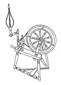
Figure 11: On a table. A horizontal bobbin and flyer wheel with treadle. The drive wheel and mother of all (with bobbin and flyer and basket distaff) are mounted on a slightly angled three-legged table.
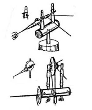
Figure 10, top to bottom: direct drive, bat’s head, Minor’s head.

Transition from hand spindle to mounted spindle. 1 images.
1) Spindle & whorl, vertical.
2) Spindle & pulley, vertical.
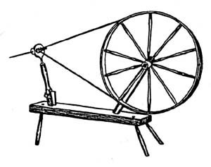
3) Spindle & pulley, mounted horizontally.
4) Spindle and pulley, mounted horizontally; pulley is connected to larger wheel via a drive band.
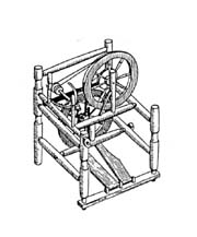
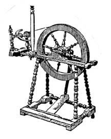
Figure 17: Double wheel/double treadle. Two drive wheels are mounted, one above the other, but slightly offset both horizontally and vertically. Below the drive wheels are two treadles. There is a single bobbin and flyer on the side of the wheel frame.
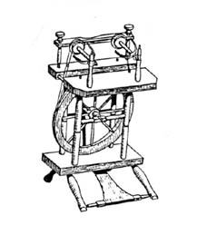
Figure 16: Double flyers. A wheel with two flyers mounted on a table above a table-mounted drive wheel with treadle.
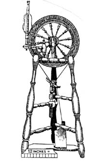
Figure 15: Bobbin/flyer below drive wheel. A horizontal arrangement with the drive wheel at the top. A distaff is attached to the 3-legged frame near the supports for the drive wheel. The bobbin and flyer is about half way between the drive wheel and the treadle.
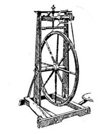
Figure 14: On a frame. A rectangular frame supports the axle for a horizontally-arranged bobbin and flyer wheel. The drive wheel is parallel to the long side of the rectangular floor supports. The bobbin and flyer mounted across the width of the frame, perpendicular to the drive wheel.

Figure 13: On a table. A small table just above the treadle holds the supports for the drive wheel. The mother of all is mounted above the drive wheel.
Wheel with horizontal spindle alignment. A great wheel-style spinning wheel, with a table-mounted spindle and drive wheel.
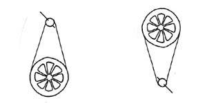
Vertical spindle alignments. A spindle with a pulley is attached via a drive band to a drive wheel.
Left: Spindle above drive wheel.
Right: Spindle below drive wheel.
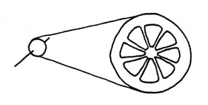
Horizontal spindle alignment. A spindle with a pulley is attached via a drive band to a drive wheel. The spindle is at about 9 on a clock face; the drive wheel is at about 3.
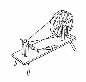
Horizontal bobbin and flyer wheel
from the collection of Michael Taylor. The wheel has a treadle connected to the drive wheel. There is a distaff attached to the table, near the bobbin and flyer.
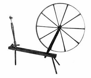
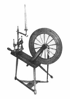
Horizontal spindle wheel from
the collection of Michael Taylor. Large drive wheel and horizonally-mounted spindle. The wheel and spindle are mounted on a table. There is no hand crank attached to the drive wheel.
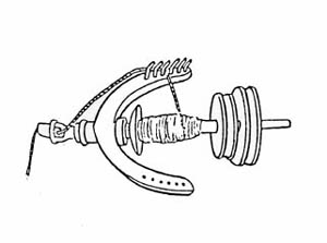
Bobbin and flyer assembly.
European spinning wheel. Horizontally mounted spindle connected to the drive wheel via a drive band. The drive wheel has a flat, wide, solid rim. The drive wheel and the spindle are mounted on a table, which has legs. The drive wheel is connected to a hand crank.
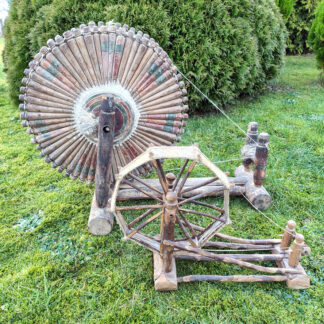
Indian spinning wheel. Horizontally-mounted spindle connected to a wheel with 8 doubled spokes. The “rim” of the wheel is made of rope or twine that is attached between the doubled spokes. The center of the wheel is connected to a hand crank.